


Glass-lined reactors and their components have been geometrically defined in technical standards (mainly DIN and DIN EN standards) for many decades. For example, the main dimensions of glass-lined reactors in the volume range from 63 to 40,000 l are defined in DIN 28136-1. The nozzle patterns for the corresponding apparatus sizes can be found in DIN 28136-3. Further standards defining the geometry of glass-lined components are listed in Figure 1 below.
In the 80's of the last century, a manufacturer-independent standardization was promoted in the former Federal Republic of Germany, in particular by the then large chemical industry, in order to establish the interchangeability and the manufacturer-independent comparability of different offers.
In addition, a large number of quality and tolerance standards were developed, enabling quality requirements to be effectively and unambiguously agreed between customer and manufacturer.
In the meantime, the basic features of many German standards have also been adopted in standards bodies of other countries or standardized at European level. In other countries, the direct use of DIN standards has become established.
THALETEC has been working in the standardization committees of DIN for many years in order to incorporate its own know-how and expertise into the standardization work.
Standards and manufacturer-independent norms ensure the long-term interchangeability of existing equipment with new equipment in the field of glass lined apparatus. Furthermore, manufacturer-neutral standardization can ensure that new spare parts for existing apparatus are guaranteed to "fit".
On the other hand, strict compliance with standard specifications also has disadvantages:
- Standardized components and equipment do not always meet the requirements of special applications, such as the manufacture of active pharmaceutical ingredients. GMP and purification requirements are difficult or impossible to achieve with DIN containers.
- The "environment", i.e. the installation situation and the connection points to standardized enameled equipment, must be adapted, which can often lead to suboptimal solutions, complex piping, cleaning problems, etc.
- Often the installation situation in the process plant requires an adaptation of the apparatus and thus a deviation from the standard specifications.
- Optimization of the process is only possible within narrow limits.


DIN 28136 Part 1 specifies the main dimensions of glass lined reactors. Basically, the standard distinguishes between three designs: AE, BE and CE vessels. In the case of the AE vessel, the reactor consists of a lower vessel with a main flange in the diameter of the reactor and a corresponding cover with a nozzle pattern. Reactors of this design are standardized from 63 to 6300 liters. In practice, however, AE type vessels are rarely made larger than 1000 l (diameter 1200 mm).
The BE design is the dominant design of glass lined vessels in Europe and increasingly also worldwide. BE vessels are characterized by the fact that the largest opening on the reactor is the manhole. BE vessels are standardized from a nominal volume of 1600l up to 40000l. However, due to appropriate manufacturing and glasslining processes, BE vessels are nowadays also manufactured from 630l upwards. In this case, the nozzle pattern and main dimensions of the corresponding AE vessels serve as the basis for the reactor design. The greatest advantage of a BE vessel over all other designs is the fact that the size of the largest nozzle seal is limited to the size of the manhole and a reliable seal of the reactor can always be guaranteed. It should be noted, however, that BE vessels require special mixing systems such as the THALETEC Multiflex or CryoTec system: agitator shaft and turbine must be detachably connected.
As a third type of glass lined apparatus, there are vessels of the CE type. These have a large mounting opening on which the stirrer drive is mounted. The mounting opening is necessary to be able to install the (one-piece) stirring element. CE stirred vessels are standardized for volumes from 1600l up to 40000 l.

Analyzing THALETEC's customer orders of the past years, it can be stated with regard to "compliance with standards" that the most frequent modifications to glass lined stirred vessels concern the following areas:
- Design pressure in the glass lined inner vessel and/or in the shell chamber.
- design temperature
- the nozzle pattern of the glass lined inner vessel: size, number and position of nozzles at the top bottom, including the size of the manhole opening
- main dimensions, especially the length of the apparatus
- additional (off-center) nozzles at the bottom of the vessel
- additional nozzles in the jacket area of the stirred tank
- the position and number of the shell nozzles
- the supporting structure
Design pressure and/or temperature
Common "standardized" glass lined stirred vessels are designed for pressures of -1/+6 bar in the inner vessel and in the outer shell area for a temperature range of -60°C to +200°C and the wall thicknesses are dimensioned and standardized accordingly.
In some cases, customers deliberately deviate from the "usual" design conditions, with deviations relating to the design temperatures occurring more frequently than those relating to the pressure range.
Increasing the design pressure
Increasing the design pressure of the equipment (inner vessel and outer shell) results in an increase in the wall thicknesses of the pressure-bearing components. As an example, consider a calculation for a BE 6300 vessel to DIN 28136. If the permissible operating pressure of the apparatus is increased to values above 6 bar, the increases in the wall thicknesses of the inner vessel (IK) and outer jacket (AM) shown in Figure 4 result:

Figure 5 shows, as an example for a BE 6300 reactor to DIN 28136, the increase in the wall thicknesses of the inner vessel and outer jacket when the design temperature is increased from 200°C to up to 300°C. Since the yield strength of the equipment’s material decreases with increasing temperatures, the wall thickness of the reactor (outer jacket) increases by up to 15% (at a design temperature of 300° compared with 200°C).
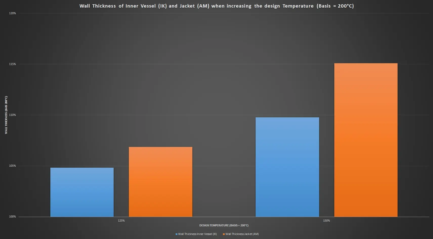
If not only the design temperature but also the actual operating temperature is to be higher than 200°C, further measures are required.
Effect on supporting structure and costs
All the above-mentioned modifying measures, such as increasing the pressure, lengthening the apparatus and increasing the design temperature, lead to an increase in wall thickness and thus to an increase in the weight of the equipment. Lengthening the reactor body also leads to a larger possible filling volume and thus also to an increase in weight. The increase in weight is essentially linear with the wall thicknesses and also linear with the reactor’s volume. The higher weight must be taken into account in the dimensioning of the supporting structure and may also lead to reinforced designs.
The above-mentioned modifying measures also have an influence on the cost of the reactor. The costs increase essentially linearly with the wall thickness of the tank (material input). Further non-linear influences result from the additional engineering effort, adaptation of the supporting structure as well as any necessary modifications and adaptation of the installation parts (agitator, baffle, etc.).
Nozzle pattern
The nozzle pattern defines the number, size and position of the nozzles on the upper dished head of the glass lined reactor. DIN 28136-3 specifies in detail the standard for AE, BE and CE type apparatus. In practice, however, more than 80% of the glass lined stirred vessels manufactured by THALETEC are designed with a "modified nozzle pattern". The modifications concern (in descending order of frequency):
- The number of nozzles
- The nominal diameter of the nozzles
- The angular position of the nozzles
The number of nozzles on the upper dished head is the most frequently modified by the customer compared to the requirements of the relevant DIN standards. The larger the machine, the more nozzles fit on the upper bottom and the more this option is used. Increasing the number of nozzles also makes sense in many cases: the piping of the apparatus in the plant is simplified, and distributors or so-called "deer antlers", with which several pipes are brought together on one vessel nozzle, become unnecessary.
In addition, nozzles can be optimally positioned with regard to their task or use. Many reactors that are to be equipped with CIP cleaning systems have, for example, two to three nozzles on an inner pitch circle (Fig. 6). CIP cleaning systems such as the THALETEC HydroCIPPY GL (Flyer K149) are later built on this.

In some cases, the nominal diameters of the nozzles are also adjusted compared with the standard specifications and larger nominal diameters tend to be specified. This can be useful for several reasons. For example, baffle nozzles can be enlarged in order to install larger and thus more effective baffles. Alternatively, larger baffles allow the installation of larger power baffles (see flyer Flyer K018), to further accelerate the heating and cooling processes in the reactor.

Finally, every now and then the position of the nozzles at the top bottom is changed because the apparatus has to be adapted to the local conditions and the piping layout.
In the case of a desired modification of the nozzle pattern on the upper bottom, it must be ensured that this modification has been tested and approved by THALETEC. For example, the minimum spacing of nozzles is determined, among other things, by the thickness of the upper base; if nozzles are too close to each other, greater wall thicknesses than those of standardized bases may be required. This can have an impact on the procurement time and thus the delivery time.
Larger manhole openings – Better safe than sorry
In the case of glass-lined reactors, the sizes of the manholes (access opening) are also standardized and assigned to the apparatus sizes. For example, the BE 1600 apparatus is to be designed with a DN350/450 manhole opening in accordance with DIN 23136.
However, the customer's wish today is to install manhole openings that are as large as possible in order to meet the increased safety requirements when entering the reactor for service or inspections.
Thanks to a special manufacturing method, THALETEC is able to produce such an apparatus with a manhole opening of DN 500.
On request, THALETEC also supplies apparatuses from size BE 4000 up to BE 6,300, all of which have a DN 500 manhole in accordance with the standard, with DN 600 manhole nozzles.
Additional nozzles at the bottom dished head
In rare cases, the process in the agitated vessel requires an additional nozzle in the lower bottom. This nozzle can be used, for example, for the installation of a temperature measuring probe or for the introduction of gases via a gas dispersing valve (see K083). The additional nozzleis usually positioned off-center, while the discharge connection piece remains positioned centrally to the tank axis. It should be noted that with additional nozzles on the lower bottom, the encased surface area is smaller than with a simple centric nozzle and thus the heating and/or cooling capacity is reduced. To compensate for this, it is often useful to use a PowerBaffle (see Data Sheet K018), which more than compensates for the loss of surface area and significantly increases the thermal performance of the reactor.

Side nozzles are very rarely used. The reason for this is that such nozzles, if they are located in the jacketed area of the glass lined vessel, have to be routed through the jacket space at great expense. Corresponding recessed areas reduce the heating/cooling surface of the reactor. Finally, lateral nozzles in the glass lined inner vessel also influence the flow profile of the heating/cooling media in the shell space and change the flow pattern, despite the use of flow nozzles (Flyer K062).


Main dimensions
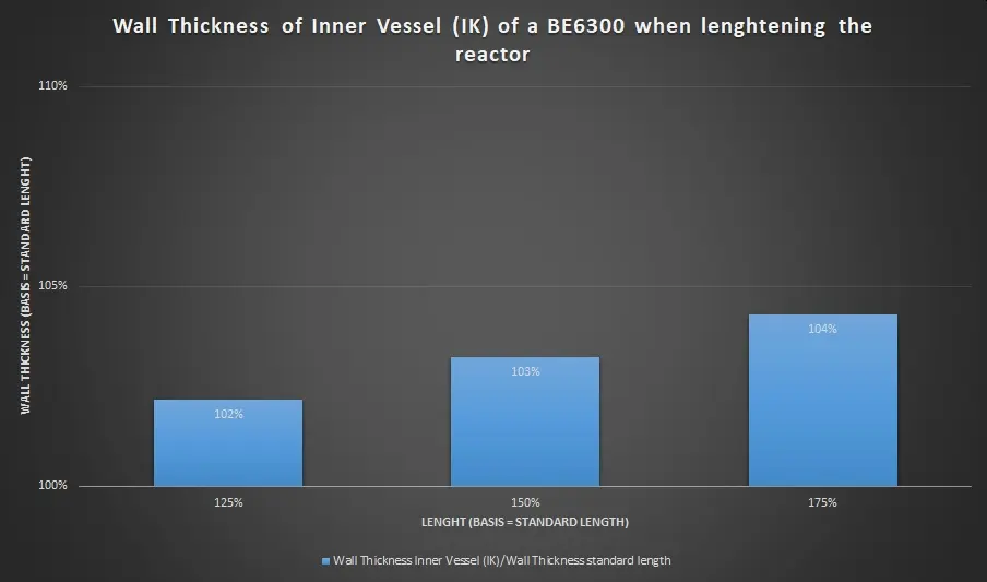
The DIN 28136 standard specifies the main dimensions (diameter as well as length of the glass lined reactors) for agitated reactors. In some cases, the customer wishes to deviate from these specifications. The diameter of the vessel is usually not changed, but in many cases the length of the reactor is. By increasing/decreasing the length, the useful volume of the apparatus can be adapted within certain limits without requiring major changes to the plant or infrastructure.
If a reactor is to be lengthened compared to the specifications of the standard, this usually leads to a new calculation of the wall thicknesses of the tank frame (this is the cylindrical area of the stirred tank) and the wall thickness of the shell in the case of jacketed reators.
Furthermore, the agitator and the built-in parts, such as the baffles, must be checked with regard to mechanical strength and vibration behavior: Lengthening a stirrer shaft reduces the critical speed of the stirrer, at which potentially dangerous oscillations of the stirrer shaft can occur. In the case of the baffle, the applied loads increase proportionally to the length and cause a higher bending moment at the nozzle flange. In addition, the critical excitation frequencies due to vortex formation must also be considered for the baffle.
Further modifications
The modifications described so far mainly concern the so-called "inner keel" of the glass lined stirred tank. If such modifications or adaptations are necessary, they must be specified at a very early stage during order processing, ideally already when the order is placed, since the glass lined inner vessel is the component that determines the delivery time. Adaptations in the areas of
- supporting structure
- shell nozzle
Can often be defined or adapted later in the manufacturing process.
Support structure
Supporting structures are defined in several standards, depending on the design:
- Support brackets in DIN 28145-7
- Support rings in DIN 28145-4
- Feet in DIN 28145-4
In practice, however, it is the case that the reactor must be integrated into existing installations. In order to avoid structural measures in the plant, it is advisable to adapt the supporting structure of the container to the surroundings.
As described above, the support structure must also be adapted if the weight of the apparatus increases as a result of changes in operating pressure, calculation or operating temperature, or the length of the apparatus.
Jacket nozzles
The type, number and position of the shell nozzles of glass-lined apparatus are specified in DIN 28151 and depend, among other things, on the size of the reactor and the supporting structure. Here, too, it is easy to make adjustments or deviating specifications during order processing, which are then taken into account in the manufacture of the equipment.
Conclusions
Modification, i.e. targeted deviation from the specifications of the standard designs of glass lined reactors, can be useful in many cases. However, there are a number of things to consider when making modifications, which makes competent advice from a specialist company such as THALETEC highly recommendable. However, if all aspects are analyzed systematically and implemented accordingly, the customer receives a reactor that "fits like a glove".