


The „optimised agitator speed“– a greater heat exchange is physically not possible!

Introduction
Glass-lined reactors are used in the chemical and pharmaceutical industries to allow complex processes with aggressive media. A decisive aspect is the product temperature adjusted via various heat flows. Reaction heat that occurs must be dissipated with sufficient safety or the product must be tempered (cooled/heated) to activate or support chemical processes. Glass-lined reactors from THALETEC GmbH offer a wide range of options for providing the necessary heat flows. Besides a jacket or a half-pipe coil, which can be additionally divided into different heating or cooling zones, THALETEC is the only manufacturer in the world offering the option of glass-lined tube bundle heat exchangers (PowerBaffle) for significantly increasing the heat exchange surface within an reactor. A PowerBaffle includes the functions of a heat exchanger, baffle and temperature sensor.
Analytics for heat transfer
In general, thermal engineering is a strongly empirical and experimental science and dimensionless parameters characterise the analysis, such as the Nusselt, Reynolds or Prandtl number. A basic set of formulas for calculating the heat transfer in reactors can be found in the “VDI-Wärmeatlas” [1]. Among other things, it presents the theories for calculating the heat transfer of a jacket or a half-pipe coil to the outer wall of the vessel, as well as the heat conduction through a glass-lined steel wall. The heat transfer on the product side to the inner wall of the vessel is only given in general terms and for exemplary agitator systems defined by dimensionless parameters. Individual calculations depending on the manufacturer-specific agitator systems and the data of product and service media are therefore inevitable. At this point, the know-how of THALETEC can be relied upon.
Heat flow via a jacket, half-pipe coil or a PowerBaffle
Due to the temperature difference of the product and service media (thermal potential) and depending on the prevailing flow velocities, the heat flow through the glass-lined steel walls is set. Depending on the thermal task, common service media are thermal oils, water-based media or steam.
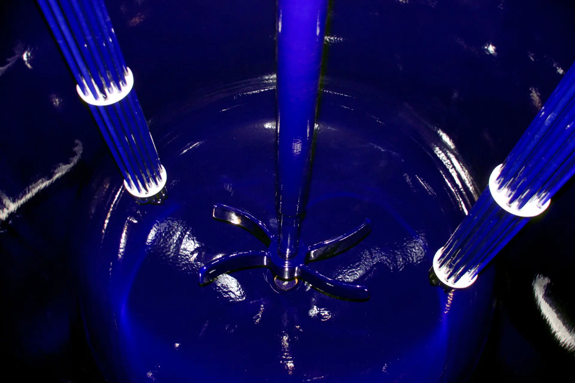
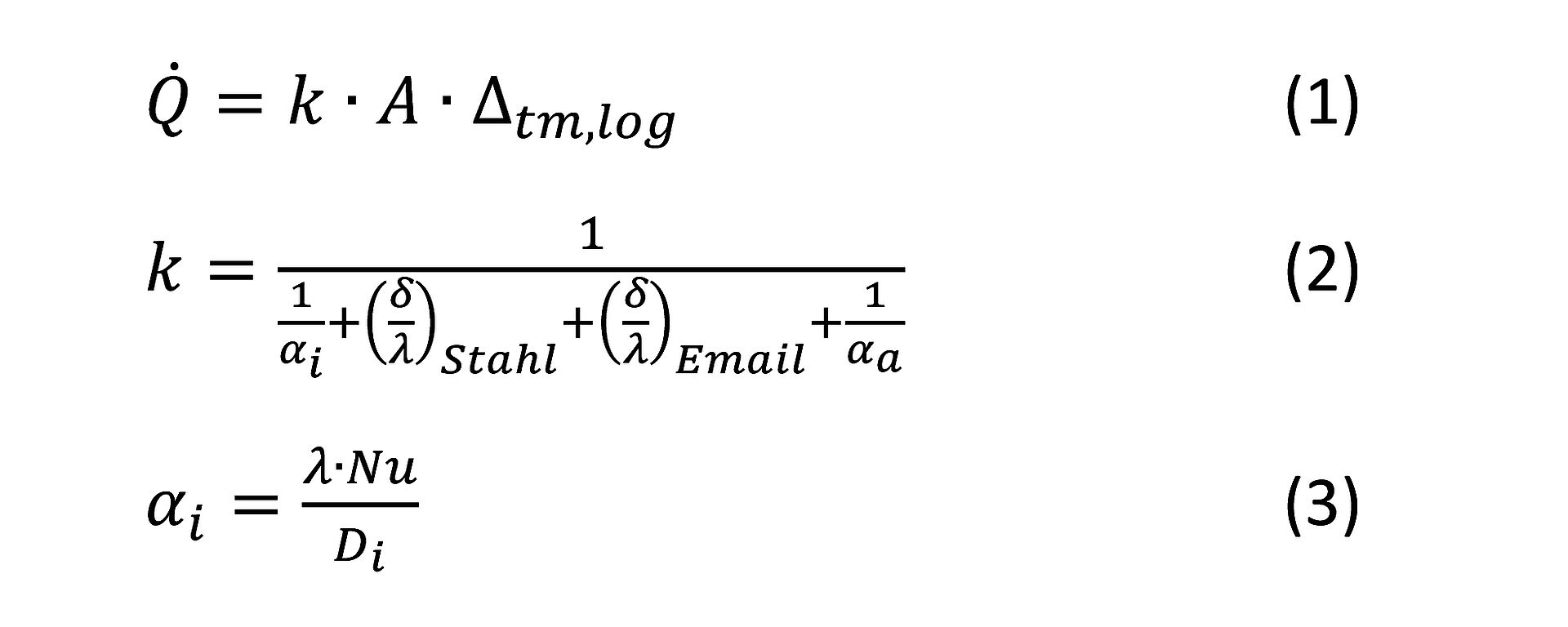
To determine the heat flow (1) of the jacket or the half-pipe coil as well as the PowerBaffle (Figure 1), the k-value (2) must be determined in each case and multiplied by the heat exchange surface and the logarithmic temperature difference.

The k-value depends on the wall thickness of the steel wall and the glass-lined layer thickness as well as their thermal conductivities. Furthermore, technical know-how is necessary to determine the heat transfer coefficient (3). With regard to the inner vessel (i), it depends on geometric and product parameters as well as the agitator system, respectively the flow conditions. These aspects are reflected by the Nusselt number (Nu) based on corporate know-how. The heat transfer coefficient (a) of the outer vessel (jacket/half pipe coil) and the inner tube side of the PowerBaffle is sufficiently known from the literature, but also includes empirical and dimensionless parameters.
Power input of the agitator system
The power input depends on the product properties processed in the reactor and the agitator system (turbine and baffles). If operation in the turbulent range is assumed, the product density has a linear influence on the necessary power of the drive. The viscosity is negligible and only relevant in the laminar range. In addition, the agitator speed and the turbine diameter have a significant influence on the power input, as they are depend to the 3rd and 5th power!

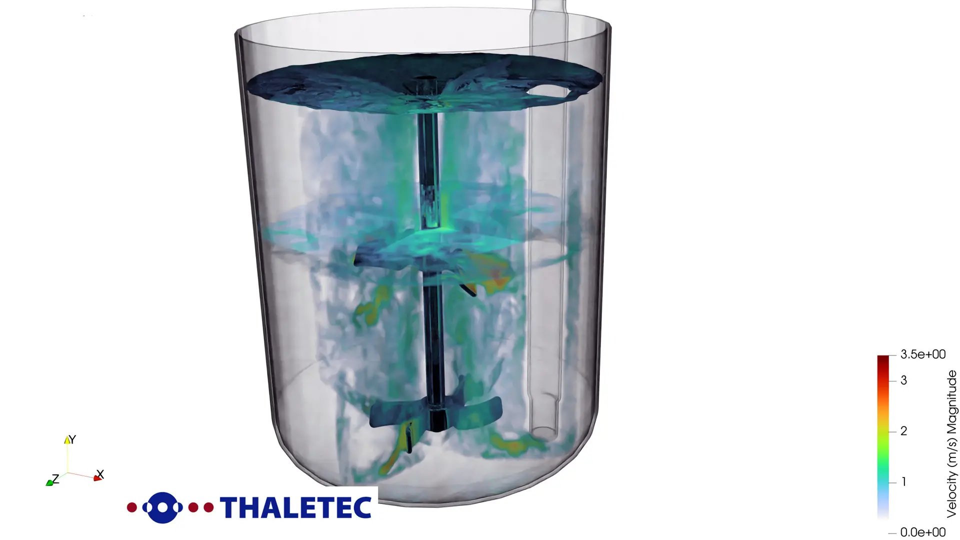
All other aspects, such as the geometry and number of turbines, as well as the type and number of baffles and the distance to the bottom, are represented by the dimensionless Newton number, which can be determined experimentally or with the help of CFD (Computerised Fluid Dynamics) (Figure 2). At this point, THALETEC's know-how can be used to determine or calculate the characteristics of the agitator system such as the power input, the shaft torque, the specific power input or the critical suspending speed as well as the circulation power and time of the individual agitator system.
In order to realise individual process conditions, THALETEC offers a variety of different agitator systems (turbines and baffles). The range covers a broad spectrum from low (low power input, low shear effect) to high Newton numbers (high power input, high shear effect).
The „optimised agitator speed“
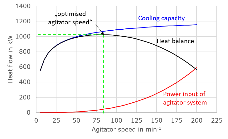
As described, in addition to the heat transport via the service media, a further power input (heat input) takes place via the agitator system. In the case of cooling via the service media, both aspects have an opposite effect. Both the cooling via the service media and the power input via the agitator system are speed-dependent and a maximum heat flow that can be dissipated is set as a function of the agitator speed - the optimised agitator speed.
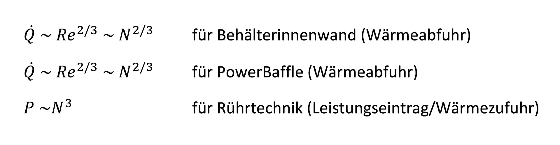
It is known from analytics that the speed dependence of the heat dissipation via the service media follows a root function. In contrast, the power input of the agitator system follows a power function, so that the difference of the two equations shows an optimum (Figure 3). At this "optimal" speed, the greatest heat flow can be dissipated from the reactor. Higher speeds increase the heat input through the agitator disproportionately compared to the increase in cooling capacity. Consequently, the heat flow that can be dissipated decreases for physical reasons. If greater heat dissipation or cooling capacity is desired, this can only be achieved via additional heat exchange surfaces, such as a PowerBaffle.
Es ist anzumerken, dass die „optimierte Rührerdrehzahl“ lediglich ein Optimum aus wärmetechnischer Sicht widerspiegelt! Weitere prozessspezifische Aspekte, wie der notwendige Leistungseintrag, die Strömungsverhältnisse bzw. Umwälzleistung, die Betriebskosten oder die kritische Drehzahl (1. Eigenfrequenz des Rührsystems) zur Vermeidung von Schwingungen, sind zu beachten und haben meist Vorrang.
THALETEC bietet Ihnen die Berechnung und Beurteilung der aufgeführten Aspekte zur optimierten Rührerdrehzahl an ().
Ein Blick in die Zukunft
Freuen Sie sich auf weitere Artikel in den folgenden Newslettern zu energetischen Themen, unter anderem: Heizen und Kühlen beschleunigen und dabei Energie sparen (PowerBaffle)
Literaturverzeichnis
[1] VDI-Gesellschaft: VDI-Wärmeatlas. Berlin: Springer Berlin Heidelberg, 12. Auflage, 2018