


THALETEC RefPoints – always measure at the same point

In many cases, one would like to estimate the condition and the expected service life of an glass-lined equipment or the glass-lining. This is possible by measuring and extrapolating the glass erosion due to corrosion and/or hydroabrasion at time intervals.
Up to now, this has hardly been possible, mainly for the following reasons:
- Since the glass application is carried out at the manufacturer's by means of an artisanal process, the layer thickness of the enamel coating can vary within up to one mm; this range of variation is permissible according to the relevant quality standards for glass-lined apparatus and components.
- The glass removal due to corrosion or erosion is not the same everywhere in the vessel. Often the glass removal in the gas space of the vessel is different from that in the area in contact with the liquid.
- In order to detect trends, measurements would have to be taken repeatedly at exactly the same points; since there are no reference points or markings on the glass-lined surface, it is impossible to find the exact same measuring point again for a coating thickness measurement.
THALETEC RefPoints - the simple solution to an old problem
The problem of precisely finding a specific point on the surface of a glass-lined surface has now been solved in a simple way by THALETEC:
The principle is simple: geometrically precisely defined recesses, so-called refpoints, are made at "interesting" or representative points on an enameled reactor, tank or component before enameling.
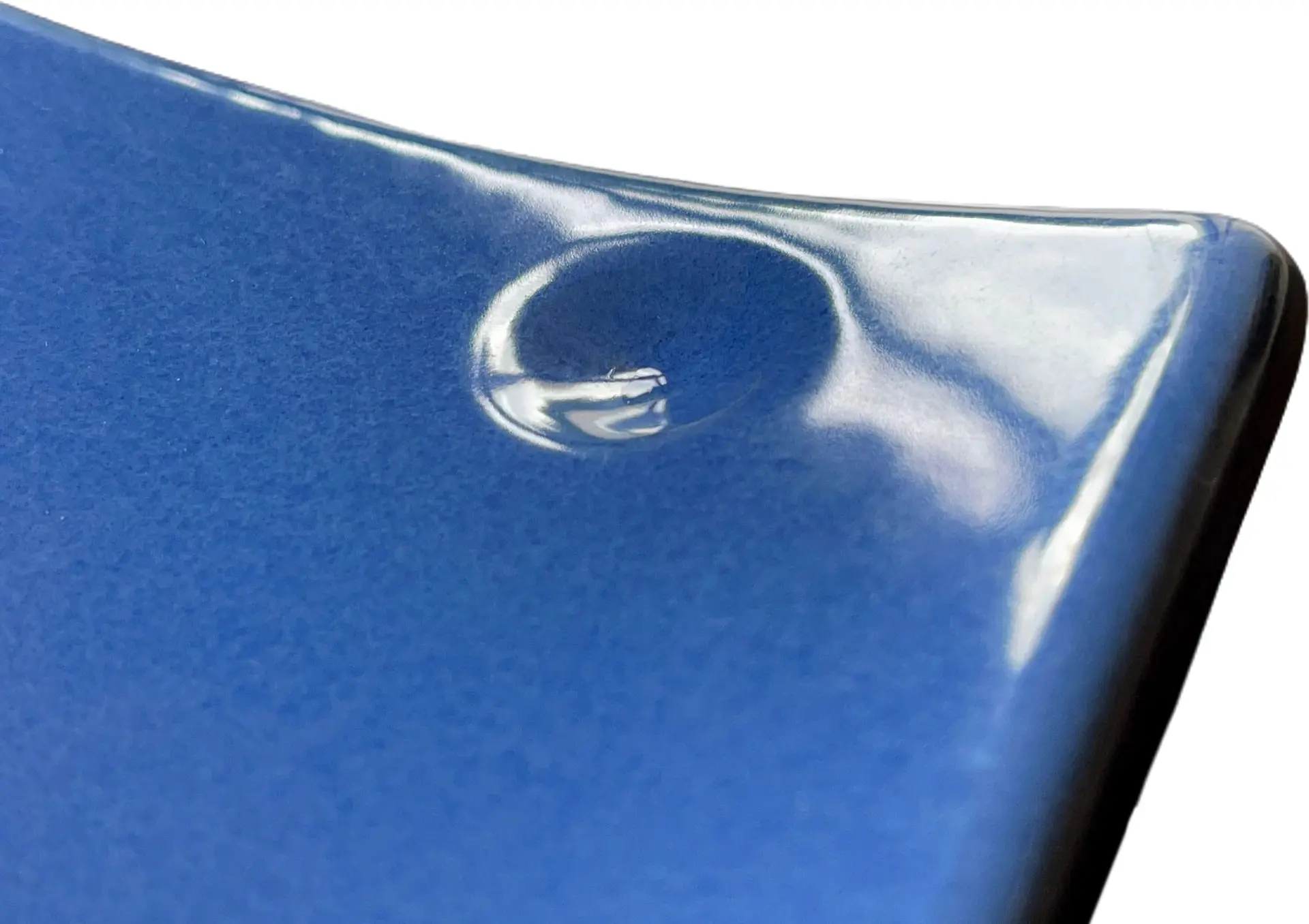
These indentations are designed in such a way that they have no influence on the durability of the glasslining or on the mechanical properties of the component. The entire component is now glass-lined and tested in accordance with the criteria of the relevant international quality standards. The recesses are also glasslined in accordance with the standards. Therefore, the service properties of the apparatus or component are not restricted.
For the safe performance of repeatable measurements at one and the same point, three RefPoints are attached to the vessel wall or the glass-lined component in a precisely defined triangular arrangement.
Three recesses in the form of an asymmetrical triangle with precisely defined leg lengths are made at the respective "interesting" points on the inner surface of the glass-lined component. Three RefPoints, aligned and arranged in a defined manner, form a reference pivot point. The reference pivot point spans a statically defined tripod, whereby, for example, the point of intersection of the gravity axis of the triangle with the component surface forms a fixed and precisely reproducible and localizable point of intersection.
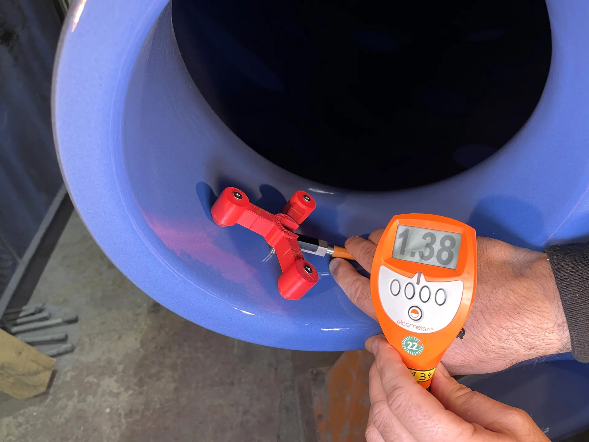
This intersection now serves as a reference point for various measurements in the reactor or tank or on the component. With the aid of a measuring device and a commercially available coating thickness gauge, for example, the enamel coating thickness can always be measured reproducibly at the same point; this enables a trend statement to be made for the enamelling of the entire apparatus.
It is also possible to measure the wall thickness of the vessel (see flyer K155) at reproducible measuring points.
Reference triple points how many and where?
From years of experience in the reglassing of hundreds of customers' equipment, we recommend the reference pivot points listed in the table below:
| Component | Recommended position of the reference pivot points |
|---|---|
| Agitated Reactor | Cylindrical area at the top, in the gas space of the reactor Cylindrical area of the vessel in the temperated area (preferably center of the cylinder) In the area of the brim of the lower bottom In places which are/will be judged as representative or "critical" on the basis of the customer's operating experience. |
| Horizontal Tank | In the cylindrical area of the vessel at the bottom, halfway up the filling level and at the top. At points which are/will be judged as representative or "critical" on the basis of the customer's operating experience. |
| Vertical Tank | Cylindrical area at the top, in the gas space of the vessel Cylindrical area of the vessel in the tempered area (preferably center of the cylinder) In the area of the brim of the lower bottom At points which are/will be judged as representative or "critical" on the basis of the customer's operating experience. |
| Baffle, Dippipe, Feed Pipes | At the upper end (approx. 150- 200 mm below the flange of the component. Approx. 100 mm above the lower end of the component on the flow-facing side |
| Agitator Shaft | Approx. 400 mm below the base flange of the mechanical seal |
| Turbine | On the upper side facing away from the flow or on the rear side of at least one agitator blade in the area of the agitator blade tip |
Reference pivot points for new equipment and reglassings
Reference pivot points can be applied to newly manufactured equipment and components as well as prior to reglassing. Reference triple points can also be realized on selected components during local repairs using the LocaRep process (Flyer K112). It is not possible to "retrofit" reference pivot points on equipment that is already in operation.
Further information can be found in Flyer K160.